Sunday, January 4, 2015
Friday, January 2, 2015
Diesel engine
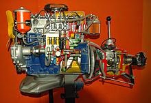
Diesel engine model, form left side
p-V Diagram for the Ideal Diesel cycle.
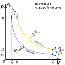
The cycle follows the numbers 1-4 in clockwise direction. In the diesel cycle the combustion occurs at almost constant pressure and the exhaust occurs at constant volume. On this diagram the work that is generated for each cycle corresponds to the area within the loop.
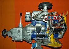
Diesel engine model, from right side
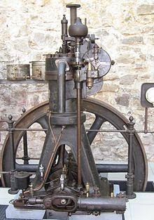
A Diesel engine built by MAN AG in 1906
Diesel generator on an oil tanker

Diesel engine:- The diesel engine (also knowns as a compression-ignition engine ) is an internal combustion engine that uses the heat of compression to initiate ignition and burn the fuel that has been injected into the combustion chamber . This contrasts with spark-ignition engines such as a petrol engine (gasoline engine) or gas engine (using a gaseous fuel as opposed to gasoline ), which use a spark plug to ignite an air-fuel mixture. The diesel engine has the highest thermal efficiency of any standard internal or external combustion engine due to its very high compression ratio and inherent lean burn which enables heat dissipation by the excess air. A small efficiency loss is also avoided compared to two-stroke non-direct-injection gasoline engines since unburnt fuel is not present at valve overlap and therefore no fuel goes directly from the intake/injection to the exhaust.
Diesel engines are manufactured in two-stroke and four- stroke versions. They were originally used as a more efficient replacement for stationary steam engines . Since the 1910s they have been used in submarines and ships. Use in locomotives, trucks, heavy equipment and electricity generation plants followed later. In the 1930s, they slowly began to be used in a few automobiles.
The world's largest diesel engine is currently a Wärtsilä- Sulzer RTA96-C Common Rail marine diesel of about 84.42 MW (113,210 hp) at 102 rpm [4] output. [5]
The diesel internal combustion engine differs from the gasoline powered Otto cycle by using highly compressed hot air to ignite the fuel rather than using a spark plug ( compression ignition rather than spark ignition ). In the true diesel engine, only air is initially introduced into the combustion chamber. The air is then compressed with a compression ratio typically between 15:1 and 22:1 resulting in 40-bar (4.0 MPa; 580 psi) pressure compared to 8 to 14 bars (0.80 to 1.40 MPa; 120 to 200 psi) in the petrol engine. This high compression heats the air to 550 °C (1,022 °F). At about the top of the compression stroke, fuel is injected directly into the compressed air in the combustion chamber. This may be into a (typically toroidal ) void in the top of the piston or a pre-chamber depending upon the design of the engine. The fuel injector ensures that the fuel is broken down into small droplets, and that the fuel is distributed evenly. The heat of the compressed air vaporizes fuel from the surface of the droplets. The vapour is then ignited by the heat from the compressed air in the combustion chamber, the droplets continue to vaporise from their surfaces and burn, getting smaller, until all the fuel in the droplets has been burnt. The start of vaporisation causes a delay period during ignition and the characteristic diesel knocking sound as the vapour reaches ignition temperature and causes an abrupt increase in pressure above the piston. The rapid expansion of combustion gases then drives the piston downward, supplying power to the crankshaft.
As well as the high level of compression allowing combustion to take place without a separate ignition system, a high compression ratio greatly increases the engine's efficiency. Increasing the compression ratio in a spark-ignition engine where fuel and air are mixed before entry to the cylinder is limited by the need to prevent damaging pre-ignition . Since only air is compressed in a diesel engine, and fuel is not introduced into the cylinder until shortly before top dead centre ( TDC), premature detonation is not an issue and compression ratios are much higher.
Early fuel injection systems:-
Diesel's original engine injected fuel with the assistance of compressed air, which atomized the fuel and forced it into the engine through a nozzle (a similar principle to an aerosol spray). The nozzle opening was closed by a pin valve lifted by the camshaft to initiate the fuel injection before top dead centre (TDC). This is called an air-blast injection . Driving the three stage compressor used some power but the efficiency and net power output was more than any other
combustion engine at that time Diesel engines in service today raise the fuel to extreme pressures by mechanical pumps and deliver it to the combustion chamber by pressure-activated injectors without compressed air. With direct injected diesels, injectors spray fuel through 4 to 12 small orifices in its nozzle. The early air injection diesels always had a superior combustion without the sharp increase in pressure during combustion. Research is now being performed and patents are being taken out to again use some form of air injection to reduce the nitrogen oxides and pollution, reverting to Diesel's original implementation with its superior combustion and possibly quieter operation. In all major aspects, the modern diesel engine holds true to Rudolf Diesel's original design, that of igniting fuel by compression at an extremely high pressure within the cylinder. With much higher pressures and high technology injectors, present-day diesel engines use the so-called solid injection system
Fuel delivery:-
Diesel engines are also produced with two significantly different injection locations. "Direct" and "Indirect". Indirect injected engines place the injector in a pre- combustion chamber in the head which due to thermal losses generally require a "glow plug" to start and very high compression ratio. Usually in the range of 21:1 to 23:1 ratio. Direct injected engines use a generally donut shaped combustion chamber void on the top of the piston. Thermal efficiency losses are significantly lower in DI engines which facilitates a much lower compression ratio generally between 14:1 and 20:1 but most DI engines are closer to 17:1. The direct injected process is significantly more internally violent and thus requires careful design, and more robust construction. The lower compression ratio also creates challenges for emissions due to partial burn. Turbocharging is particularly suited to DI engines since the low compression ratio facilitates meaningful forced induction, and the increase in airflow allows capturing additional fuel efficiency not only from more complete combustion, but also from lowering parasitic efficiency losses when properly operated, by widening both power and efficiency curves. The violent combustion process of direct injection also creates more noise, but modern designs using "split shot" injectors or similar multi shot processes have dramatically amended this issue by firing a small charge of fuel before the main delivery which pre-charges the combustion chamber for a less abrupt and in most cases slightly cleaner burn. A vital component of all diesel engines is a mechanical or electronic governor which regulates the idling speed and maximum speed of the engine by controlling the rate of fuel delivery. Unlike Otto-cycle engines, incoming air is not throttled and a diesel engine without a governor cannot have a stable idling speed and can easily overspeed, resulting in its destruction. Mechanically governed fuel injection systems are driven by the engine's gear train . [42] These systems use a combination of springs and weights to control fuel delivery relative to both load and speed. [42] Modern electronically controlled diesel engines control fuel delivery by use of an electronic control module (ECM) or electronic control unit (ECU ). The ECM/ECU receives an engine speed signal, as well as other operating parameters such as intake manifold pressure and fuel temperature, from a sensor and controls the amount of fuel and start of injection timing through actuators to maximise power and efficiency and minimise emissions. Controlling the timing of the start of injection of fuel into the cylinder is a key to minimizing emissions, and maximizing fuel economy (efficiency), of the engine. The timing is measured in degrees of crank angle of the piston before top dead centre. For example, if the ECM/ ECU initiates fuel injection when the piston is 10° before TDC, the start of injection, or timing, is said to be 10° BTDC . Optimal timing will depend on the engine design as well as its speed and load, and is usually 4° BTDC in 1,350-6,000 HP, net, "medium speed" locomotive, marine and stationary diesel engines. Advancing the start of injection (injecting before the piston reaches to its SOI-TDC) results in higher in-cylinder pressure and temperature, and higher efficiency, but also results in increased engine noise due to faster cylinder pressure rise and increased oxides of nitrogen (NO x ) formation due to higher combustion temperatures. Delaying start of injection causes incomplete combustion, reduced fuel efficiency and an increase in exhaust smoke, containing a considerable amount of particulate matter and unburned hydrocarbons.
Major advantages Diesel engines:-
have several advantages over other internal combustion engines: They burn less fuel than a petrol engine performing the same work, due to the engine's higher temperature of combustion and greater expansion ratio. [1] Gasoline engines are typically 30% efficient while diesel engines can convert over 45% of the fuel energy into mechanical energy [43] (see Carnot cycle for further explanation). They have no high voltage electrical ignition system, resulting in high reliability and easy adaptation to damp environments. The absence of coils, spark plug wires, etc., also eliminates a source of radio frequency emissions which can interfere with navigation and communication equipment, which is especially important in marine and aircraft applications. The longevity of a diesel engine is generally about twice that of a petrol engine [44] [ better source needed ] due to the increased strength of parts used. Diesel fuel has better lubrication properties than petrol as well. Indeed, in unit injectors , the fuel is employed for three distinct purposes: injector lubrication, injector cooling and injection for combustion.
Thursday, January 1, 2015
Four stroke diesel engine

SUCTION STROKE: With the movement of the piston
from T.D.C. to B.D.C. during this stroke, the inlet valve
opens and the air at atmospheric pressure is drawn
inside the engine cylinder; the exhaust valve however
remains closed. This operation is represented by the
line 5-1
COMPRESSION STROKE : The air drawn at atmospheric
pressure during the suction stroke is compressed to
high pressure and temperature as the piston moves
from B.D.C. to T.D.C. Both the inlet and exhaust valves
do not open during any part of this stroke. This
operation is represented by 1-2
POWER STROKE OR EXPANSION STROKE : As the piston
starts moving from T.D.C to B.D.C, the quantity of fuel
is injected into the hot compressed air in fine sprays by
the fuel injector and it (fuel) starts burning at constant
pressure shown by the line 2-3.
At the point 3 fuel supply is cut off. The fuel is injected
at the end of compression stroke but in actual practice
the ignition of the fuel starts before the end of the
compression stroke. The hot gases of the cylinder
expand adiabatically to point 4. Thus doing work on the
piston.
EXHAUST STROKE : The piston moves from the B.D.C.
to T.D.C. and the exhaust gases escape to the
atmosphere through the exhaust valve. When the piston
reaches the T.D.C. the exhaust valve closes and the
cycle is completed.
Four stroke cycle engine


FOUR-STROKE CYCLE ENGINES
1.Four Stroke Petrol engine.
2.Four Stroke Diesel engine.
1.FOUR STROKE PETROL ENGINE:-
The four stroke-cycles refers to its use in petrol
engines, gas engines, light, oil engine and heavy oil
engines in which the mixture of air fuel are drawn in the
engine cylinder. Since ignition in these engines is due to
a spark, therefore they are also called spark ignition
SUCTION STROKE::- In this Stroke the inlet valve opens
and proportionate fuel-air mixture is sucked in the
engine cylinder. Thus the piston moves from top dead
centre (T.D.C.) to bottom dead centre (B.D.C.). The
exhaust valve remains closed through out the stroke.
COMPRESSION STROKE:- In this stroke both the inlet
and exhaust valves remain closed during the stroke.
The piston moves towards (T.D.C.) and compresses the
enclosed fuel-air mixture drawn. Just before the end of
this stroke the operating plug initiates a spark which
ignites the mixture and combustion takes place at
constant pressure.
POWER STROKE OR EXPANSION STROKE:- In this stroke
both the valves remain closed during the start of this
stroke but when the piston just reaches the B.D.C. the
exhaust valve opens. When the mixture is ignited by the
spark plug the hot gases are produced which drive or
throw the piston from T.D.C. to B.D.C. and thus the
work is obtained in this stroke.
EXHAUST STROKE: This is the last stroke of the cycle.
Here the gases from which the work has been collected
become useless after the completion of the expansion
stroke and are made to escape through exhaust valve
to the atmosphere. This removal of gas is
accomplished during this stroke. The piston moves
from B.D.C. to T.D.C. and the exhaust gases are driven
out of the engine cylinder; this is also called
SCAVENGING.
Manual of four stroke petrol engine
To study of
four stroke petrol
engines.
AIM: To study of four stroke petrol
engine.
APPARATUS: Model of four stroke petrol
engine.
THEORY: The thermodynamic cycle is completed in four strokes of the piston or in two revolutions of the crankshaft.Thus , one power stroke is obtained in every two revolutions of the crankshaft.
1. WORKING PRINCIPLE OF FOUR STROKE PETROL ENGINES
There are four strokes which are as follows:
i) Suction stroke
ii) Compression stroke
iii) Expansion or working or power stroke
iv) Exhaust stroke
i) SUCTION STROKE: The suction stroke starts with the
piston at top dead centre position. During this stroke,
the piston moves downwards by means of crank shaft.
The inlet valve is opened and the exhaust valve is
closed. The partial vacuum created by the downward
movement of the piston sucks in the fresh charge
(mixture of air and petrol) from the carburetor through
the inlet value. The stroke is completed during the half
revolution (180 ) of the crank shaft, which means at
the end of the suction stroke, piston reaches the bottom
head centre position.
2.COMPRESSION STROKE: In this stroke both the inlet
and exhaust valves remain closed during the stroke.
The piston moves towards (T.D.C.) and compresses the
enclosed fuel-air mixture drawn. Just before the end of
this stroke the operating plug initiates a spark which
ignites the mixture and combustion takes place at
constant pressure.
3.POWER STROKE OR EXPANSION STROKE: In this stroke
both the valves remain closed during the start of this
stroke but when the piston just reaches the B.D.C. the
exhaust valve opens. When the mixture is ignited by the
spark plug the hot gases are produced which drive or
throw the piston from T.D.C. to B.D.C. and thus the
work is obtained in this stroke.
4.EXHAUST STROKE: This is the last stroke of the cycle.
Here the gases from which the work has been collected
become useless after the completion of the expansion
stroke and are made to escape through exhaust valve
to the atmosphere. This removal of gas is
accomplished during this stroke. The piston moves
from B.D.C. to T.D.C. and the exhaust gases are driven

Internal combustion enggines
An engine is a device which transforms one form of energy into another form.when the products of combustion generated by the combustion of fuel an air within the cylinder form the working fluid ,it is called an internal combustion(I.C.) engine.
Classification of I.C. Engines
The I.C. engines may be classified on the following basis:
1.Based on number of strokes per cycle:
(a) Two stroke engine
(b) Four stroke engine
2.Based on fuel used:
(a) Petrol engine
(b) Diesel engine
(c) Gas engine
3. Nature of combustion:
(a) Constant volume combustion-Petrol engine
(b) constant pressure combustion-Diesel engine
(c)Mixed combustion-Dual cycle engine
4.Based on cooling system:
(a) Air cooled
(b) water Cooled
(c)Evaporative cooling
5.Based on lubrication system:
(a) Dry sump
(b) Wet sump
(c) Mist
(d) Pressure
6. Based on engine speed:
(a) Low speed-upto 500 rpm. (Revolution per minute of shaft).
(b) Medium speed 500 to 1000 rpm.
(b)High speed- Above 1000 rpm.
7.Based on number of cylinders:
(a) Single cylinder
(b)Multi cylinder.
8.Based on ignition method:
(a) Spark ignition- Petrol Engine.
(b) Compression ignition-Diesel engine.
(c) Hot spot ignition.
9.Based on fuel supply system:
(a) Solid injection.
(b) multi-point fuel injection (MPFI)
10. Based on governing system:
(a) Quality governing.
(b) Quantity governing.